ESP8266 : GPIO2 challenges
How to use GPIO2 for input (with a signal that is high by default or low by default while the chip is booting) or output (whether the output is driven high or low to trigger).
Booting requires GPIO2 to be high but pulling-up disables it for various uses – especially detecting a high input signal (it’s still pulled high from boot so unless the inputting system pulls it low when it isn’t sending a high signal then this will not be readable).
The challenges are that simply using a resistor-capacitor to hold it high briefly for boot then means that switching off exposes the pin to a negative polarity voltage that exceeds the input tolerance according to the datasheet.
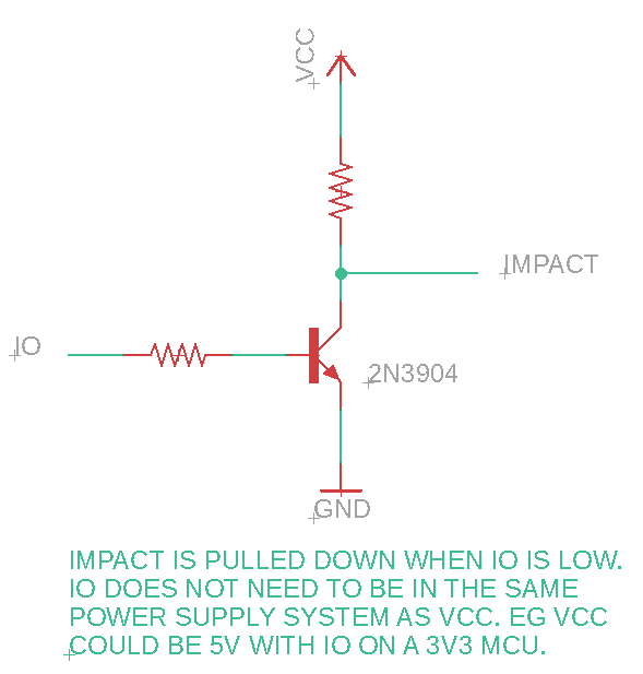
Here I test two methods of achieving this without damaging the chip – one using an RC circuit as above but with a diode to protect the reverse voltage during discharge; and one using either a NPN or PNP transistor. Which method and whether a NPN or PNP transistor is appropriate, depends on the circumstances.
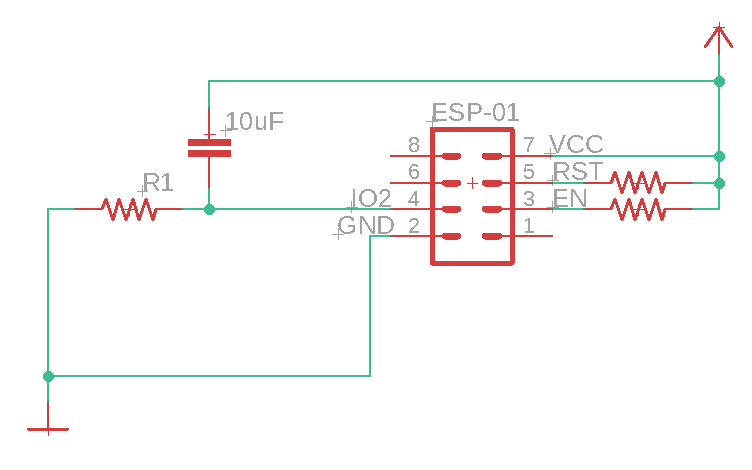
R1 boots with 56k, 47k, 33k 10k (tested but doesn’t with 1k and 4k7)
So I continued with R1 = 10k
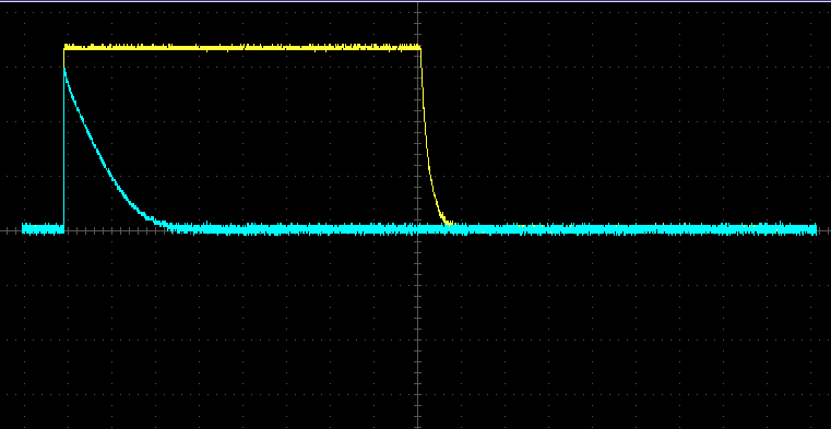
That boots fine as the pin is held high for long enough to select boot from flash:
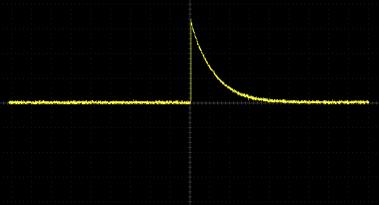
but produces a reverse polarity at the pin when powering down (ie as the capacitor discharges)
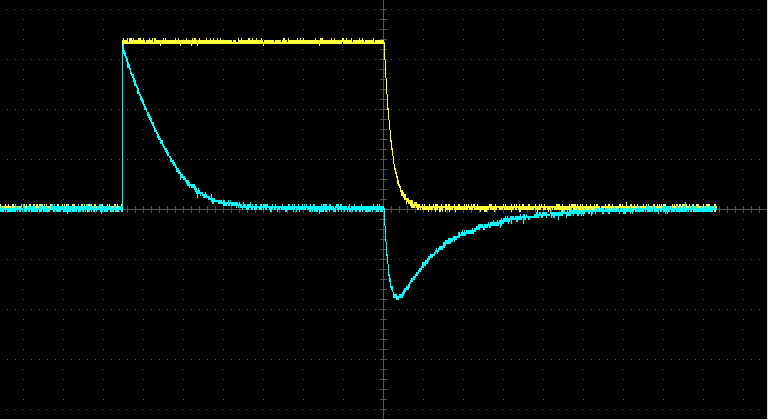
Although, through tests on this ESP-01 after removing from this circuit, I am confident this hasn’t damaged the chip – it still responds as normal and IO2 works as expected as an input and output pin. However, I’d rather find a solution that does not require accepting voltages at the pin that are outside the datasheet stated pin tolerances (-0.2V to 3.6V). So I tested this circuit:
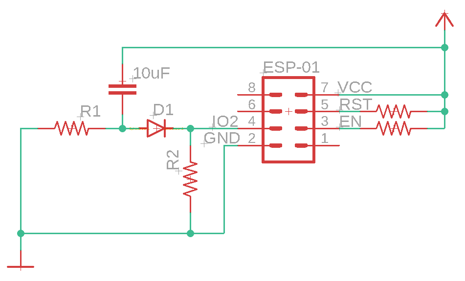
in which IO2 is high for boot (and boots successfully) but is then pulled down by R2 for use in sensing inputs that are high (and works when tested with R2 = 56k to Ground).

Equally, if R3 is moved from IO2-Ground to IO2-Vcc the circuit works in that the chip boots successfully and then IO2 is pulled up for sensing inputs that are low (working, when tested with R2 = 56k to Vcc).

NEXT TEST – can IO2 be used as an output – driving high; driving low?
Then write up the use of NPN and PNP transistors to achieve similar results in other scenarios

One Reply to “ESP8266 : GPIO2 challenges”