How to use a USB-TTL adapter to programme ESP8266 MCUs with Arduino IDE
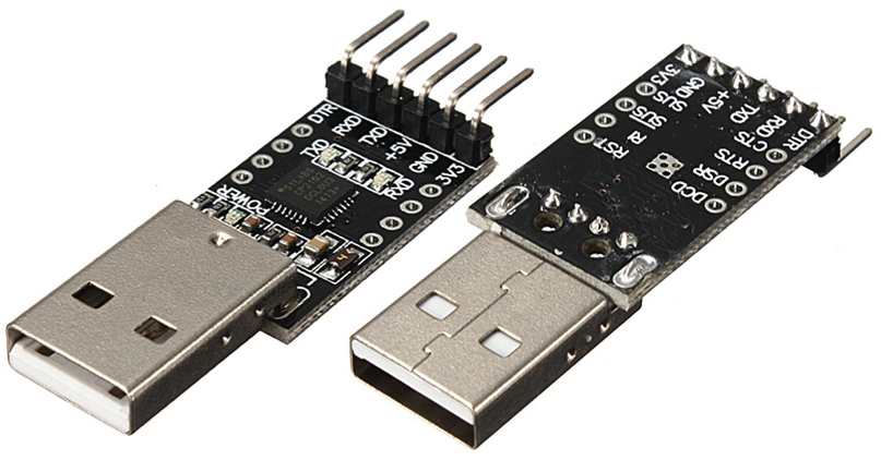
What to connect where to get a similar experience to programming an Arduino – with automatic boot selection of the ESP8266 chip to enable flashing and then re-booting into run mode after programming when using a USB-Serial adapter such as FTDI, CH340, CP210x, FT232RL etc.
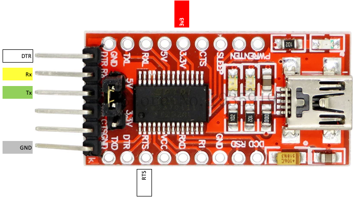
Note that some adapters have a selectable 3v3/5v jumper (don’t forget to select 3v3 so as to avoid pin over-voltages on the ESP chip).
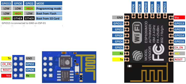
Connect the adapter’s DTR (data terminal ready) to boot select (IO0) on the ESP chip & RTS (request to send) on the adapter to RST on the ESP chip.
Pull RST and IO0 up (with 1k resistors).
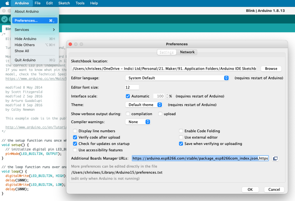
Next plug the adapter into a PC using a USB cable and select “Generic ESP8266 Module” to flash the chip
If you don’t see ESP8266 boards listed, add the following URL to the Board Manager URLs list (separate the URLs with commas if there’s more than one) : https://arduino.esp8266.com/stable/package_esp8266com_index.json