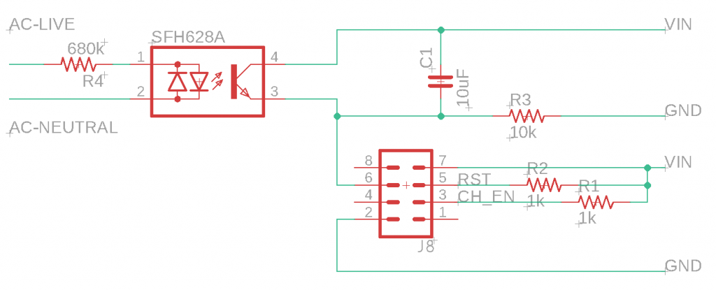
Opto-isolator (SFH628)
Definitely had it working with smooth output using 100nF & 100kΩ
and with 10µF & 10kΩ but those are not equivalent RC values so also try 1kΩ if needed for other reasons, eg below

Also now need to try with Vout feeding a microcontroller.
Which will need its input pin pulling low (so 10kΩ might need to be adjusted and then C1 might need further adjustment).
Also then need to test holding the GPIO high briefly at startup but then applying Vout, above, to it to sense it – eg ESP-01 using GPIO0 as input (as it needs to be high to boot, but pulled low to sense)
Phase 2 – feeding Vout into a microcontroller
Note that phases 2 (feed MCU) and phase 3 (holding GPIO0 high at start) ended up being the same thing as the C1/R2 RC combo provided the startup brief high required on the same pin to be used to sense. And in that respect the only combo that works for holding high at startup is C1 = 10µF & R2 = 10kΩ. 1kΩ, 2kΩ & 4.7kΩ did not work – the startup high tailed off only to about 80% and the chip didn’t boot. So going forward, trial and error efforts will be based on C1 = 10µF & R2 = 10kΩ
The below circuit booted with a test sketch running successfully (test sketch just MQTT’d ON/Off repeatedly to a debug topic so I knew it was running) and with an oscilloscope graphing Vout, and showing it successfully going high at startup, then tailing off as C1 charges, then mains voltage producing a current to Vout and taking it back high. NOTE in the below (as I started a new Eagle project R2 is now R3 and R1 is R4. NOTE also that while R1, 2 & 3 are shown as SMDs (and, therefore, less than 0.1W) R4 must be able to handle the current produced by a 220-240V supply. It works with a 1/4W so stick to a through-hole resistor.
Now need to write a script that MQTT’s on GPIO0 high.

Then need to test the whole thing using SMDs before creating a PCB. This is not a circuit to use with anything remotely development-like about it.